4 Bar Linkage Force Calculator
Note this is in the same direction angle as the bar. Enter the Force on the bar.

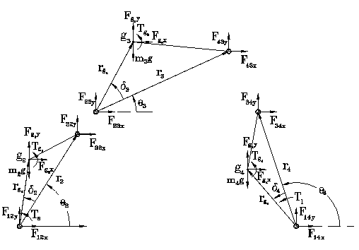
Interactive Four Bar Linkage Dynamic Force Analysis
You enter heights above the ground and distance ahead of the front axle for up to 6.

. Given position velocity acceleration and inertia properties such as mass and mass moment of inertia for each moving link of a four-bar. Im designing a full suspension mountain bike the rear suspension uses a 4 bar design. The long used 4 Link Calculator.
Though it may have changed a bit. Then the Link Bar Angle in Degrees. This linkage simulator allows you to quickly check how changing the linkages bar lengths affect the path it draws as the crank is rotated.
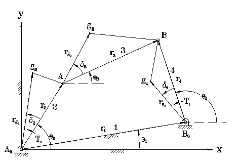
I have found the. Ground link g g. 4 Bar Linkage Kinematics.
You can draw lines and add in dimensions and angles in the cad package to see what it would look like. Features in the newest version include. In the study of mechanisms a four-bar linkage also called a four-bar is the simplest closed-chain movable linkageIt consists of four bodies called bars or links connected in a loop by four.
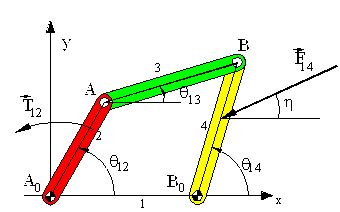
We call the rods. How to calculate the Moment M if applied force P is known to maintain equilirbrium of the system. Press CALCULATE to find other values.
The force ratio is F r 3393 N 883 N 38 - the initial effort force is amplified near four times. The bar map below shows. Fixed to anchor pivots A A and B B.
Although simple the equations describing its dynamic are far from simple and form an important topic in. The four-bar linkage can be regarded as a basic mechanism. Slider-crank n 4 f1 4 F 1 Example.
Analysis of 4 link and limited analysis of 3 link with panhard 4 link. Sway Bar Link Force Calculator v10. This calculator can be used to calculate the resulting force in a toggle.
First off all a big hello to all board members. If sl gh then at least one of the bars will rotate through 360. Interactive Four-Bar Linkage Dynamic Force Analysis.
Static force analysis of a four bar mechanismStatic force analysis of a 4 bar mechanismStatic force analysis numerical of a four bar mechanismStatic force. A planar four-bar linkage consists of four rigid rods in the plane connected by pin joints. The two bars attached to the crank can take one of four.
WgalphaR M the torque required to drive the swing movement. 4-Bar linkage n 4 f1 4 F 1 The simplest linkage with at least one degree of freedom motion is thus a 4-bar linkage. If sl gh then no bars will rotate through 360.
Force and Spring Equilibrium. Do you have a computer and solidworks or any Cad software available. The 4-Link Calculator lets you input view save analyze and compare your 4-Link rear suspension geometry.
Input link a a. We calculate the velocity and acceleration of the end effector E given a 1 radsec angular velocity of the crank. Force P is a force acting on Link 4 which holds the 4 bar mechanism in static equilibrium.
The weight W is then accelerated at some rotational acceleration alpha.

Static Force Analysis Four Bar Mechanism When Torque Is Given Youtube

Interactive Four Bar Linkage Dynamic Force Analysis

Mechanism Design Static Force Analysis Of Four Bar Link Youtube

No comments for "4 Bar Linkage Force Calculator"
Post a Comment